Rotor Blade Design
Introduction
In the section Rotor Aerodynamics we considered
the aerodynamic aspects of airfoils. We will, therefore, now look at several rotorblade designs.
Airfoil, lift and drag
Probably the single most important rotor design parameter is its Lift/Drag
ratio, which should be as high as possible.
This ratio depends on the design of the aerofoil , and before we go on to discuss a number of types, we will first introduce the fineness ratio. This is the thickness of the airfoil as a percentage of the chord length. A blade with a good L/D performance
has a fineness ratio of about 15%, with its maximum
chamber being a quarter of the way back from the leading edge. A typical L/D value for a helicopter
blade is 30:1.
, and before we go on to discuss a number of types, we will first introduce the fineness ratio. This is the thickness of the airfoil as a percentage of the chord length. A blade with a good L/D performance
has a fineness ratio of about 15%, with its maximum
chamber being a quarter of the way back from the leading edge. A typical L/D value for a helicopter
blade is 30:1.
The types of aerofoils used with a rotorblade differ (figure below). For a long time, most of them
were symmetrical. However, a higher L/D ratio is possible with
non-symmetrical versions. Due to the greater internal forces occurring in these
types of blades, they
only came into existence when the appropriate composite materials
were developed. These
can cope with the high internal strain, while their weight
is kept low.
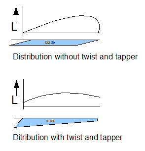
Blade twist and tapper
When a blade rotates, each point on it travels at a different speed. The
further away from the root, the higher the velocity. This means that the
contribution to lift and drag of every point on the blade differs, with each aspect getting larger
when moving closer to the rotor tip. Clearly, the lift distribution
over the blade is not constant. This is not a desirable situation, because the contribution diminishes
when getting closer to the root.
To change this distribution, blades
are twisted and, sometimes, also tapered. The twist is such that the angle of attack increases
when travelling towards the root, producing more lift. Tapering the blade also contributes
to achieving a more evenly spaced lift distribution. With
blade tapering, the blade's
surface gets larger when travelling towards its root.
Both tapering and twisting
can be observed when looking carefully at rotorblades
at rest. Note that blade tapering
is not always used (especially on metal blades because of a more complicated fabrication process).
Blade root cut out
Blade twist and taper leads to large angles of attack and large blade surfaces
at the root. However, close to the root, the blade is travelling over the hull, so
the
generated downwash does not contribute to helicopter thrust. For this reason,
rotorblades are often cut out near the root. Another reason for rotor blade cut out is
to reduce the effects of potential reverse flow (on the retreating rotorblade)
when flying at high speeds.
Twisting moments
Rotorblades are constantly strained by moments that try to twist them. This twisting
has its origins in the moments which exist between the centre of pressure (due to
the aerodynamic forces) and the mass centroid over the chord line.
The blade designer must take these twisting moments into account by designing a
blade with high torsional stiffness. He must also ensure that the mass centroid is
located ahead of the centre
of pressure for all blade angles (in its operational range). In this way, lift tends to lower the angle of attack: a stable condition.
Blade tip speed and noise reduction
When the blades are very long or the helicopter is designed with a high rotor RPM,
the blade tip speed can become extremely high. When the tip speed reaches the sound of speed,
pressure waves come into existence, which causes rotor drag. A high tip speed is also
the single most important design parameter influencing generated noise levels.
It is, therefore, logical to expect more designs with lower RPM and very efficient
(larger L/D ratio) performance blades. In this way, blade efficiency is traded off for noise
reduction instead of better flight performance.
Construction
Some important design requirements for blades are high torsional stiffness and
a good L/D ratio. Note that the weight of the rotor also has important consequences
for both the necessary engine power and stored kinethic energy (important for good auto-rotation
performance).
The early designs of rotorblades, which resemble early
classic wing design, consisted of long steel tube spars, wooden ribs
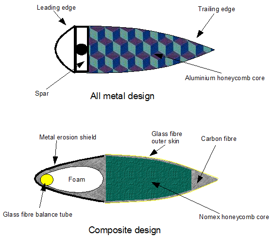
and some light surface material attached to them. From the 1960s onwards, all metal aluminium alloy blades were introduced.
These were constructed from long hollow leading edge D-spar extrusions, allied with
some light (probably aluminium) trailing edge constructions. The use of extrusions
made blade taper difficult to produce. Honeycomb constructions were added to achieve
a stiff and light construction.
These days, composite materials like fibreglass and carbon fibre are used for the
fabrication of rotorblades. Stainless steel leading edge spars are also used, and
all composite
spar designs exist too. The fatigue life properties of composite materials are far
better than those of metals. Fibreglass is used for its strength and chemical inertness.
Carbon fibre layers, sandwiched at right angles, are used to add stiffness. A sample design might look like the figure below. Generally, composite blades also
have some extra added weight (for example, at the blade's tip) in order to achieve
desirable
inertial characteristics. At the leading edge, an (often metal) erosion shield
is used.
like fibreglass and carbon fibre are used for the
fabrication of rotorblades. Stainless steel leading edge spars are also used, and
all composite
spar designs exist too. The fatigue life properties of composite materials are far
better than those of metals. Fibreglass is used for its strength and chemical inertness.
Carbon fibre layers, sandwiched at right angles, are used to add stiffness. A sample design might look like the figure below. Generally, composite blades also
have some extra added weight (for example, at the blade's tip) in order to achieve
desirable
inertial characteristics. At the leading edge, an (often metal) erosion shield
is used.
When using modern composite materials, lightning strikes have to be considered because
these are more dangerous to composite constructions. This is because of the much greater electrical resistance of composite materials compared to all metal blades.
A lightning strike on composite materials produces a lot of heat along the current’s
path, which can damage the blade significantly. In order to provide a low resistance electrical path, the solution is to have
an outside skin that possesses low electrical
resistance and connects all of the rotor segments.
Comments are disabled.