Rotordisc
Up until now we have only looked at one rotating blade, yet as we all know helicopters
come with more than one rotor, although configurations with only two blades are quite
common. Larger and heavier helicopters always use more than two blades. In
this subsection, we will look at what happens when all of the rotors are working together and are, collectively, called
the rotordisc.
1 Thrust and drag
The first observation we must make is that the total thrust of the rotordisc is built
up from the rotors, where each one adds its own generated thrust. The same holds
true for the rotordisc’s rotordrag, which is built up from each rotor adding
its rotordrag component. All of these rotordrag forces provide a force moment at
the shaft which must be overcome by the torque provided by the shaft (powered by
the transmission and engine).
2 Coning
When rotors rotate around a shaft, a force is needed to enable them to make their
circular motion. This force is known as the
centripetal force, which will become very high in a rotorsystem,
with rotation speeds in the range of 4 to 5 hundred revolutions per minute.
Another relevant
force, which mainly depends on the angle of attack, is rotor lift. The first force
will try to level the rotors, and the second will try to get the blades moving upwards
towards the (imaginary, extended) shaft axis. This leads to an effect called coning,
as the rotors make a coning angle relative to the plane of rotation.
One of the effects of coning is that the effective area of the rotordisc will decrease.
Secondly, the lift vector becomes increasingly directed to the shaft instead of being parallel
to it. In other words, rotor thrust (the vertical component of lift) decreases.
We have seen this before;
rotor RPM must always stay above its lower limit in order to have sufficient rotorthrust.
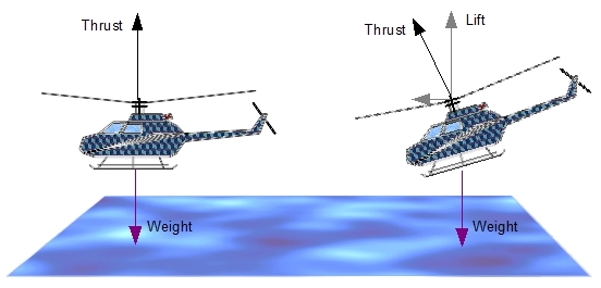
3 Rotordisc Attitude
In order to manoeuvre a helicopter, the rotordisc can be tilted in the desired direction.
This change of disc attitude enables the thrust vector to point in the direction
required. In the figure below, the thrust vector and its rotordisc attitude are
shown for both a helicopter in hover and one in forward flight. Note that in forward
flight, the thrust vector has two components: one to oppose the weight and one to maintain
forward speed. The thrust vector magnitude in forward flight must be greater because
it has to provide both the lift to oppose weight as well as forward propulsion.
When the rotordisc is tilted in one direction or another and there is a coning
angle (which is always the case), we will then encounter the phenomenon known as
the 'Hookes joint
effect'. Look at the figure and the explanation of it. It exists
because when the rotordisc is tilted, this is done not by tilting the shaft but
by tilting the rotordisc (by applying cyclic pitch control to the blades).
Thus, the rotors rotate around an (imaginary) axis that is no longer aligned with the
shaft. Note that when the rotordisc is horizontal (orthogonal to the shaft)
as it
is in the case of a hover, the Hookes’ joint effect is absent.
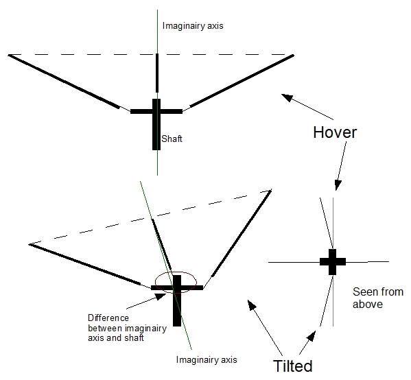
The Hookes’ joint effect means that the rotorblades will create an angle that is
not equal
to 90 degrees with the tangential line at the rotorshaft. Another way of explaining this is to say that the rotorblades have to be spaced evenly around
the circle about which the rotor
tips travel. This means that if the rotorblades were attached to the rotorshaft
in such a way that would not provide for some degree of movement in the horizontal plane,
the rotor blade would break from the shaft! The effect is caused by the fact that the centre of the circle described by the tip patch no longer
coincides with the shaft in a tilted rotordisc. The centre of the circle is moved away
from the shaft, while the points at which the rotors are
physically attached to it do not change. Because the rotors have to follow the tip path as set by the cyclic
control, they have to lead and leg as shown in the figure
which shows the rotors from above.
4 Rotordisc Inertia
The amount of inertia
a rotordisc possesses is defined by the amount of inertia of the individual rotorblade
times the number of blades. Rotordiscs can be classified as either a high or a low
inertia system. Low inertia systems are commonly found in light helicopters. It
is, however, possible to create a high inertia system by adding mass at the rotorblades’
tips, since this will increase the amount of inertia. Both classes have their pros
and cons.
High inertia
- Positives
- Smooth changes in rotor RPM as speed changes are resisted
- More kinethic energy stored in the rotor system, which helps in making flight manoeuvres
that require a lot of energy, for example the execution of a flare while in autorotation.
- Negatives
- It requires more engine power to accelerate to the desired rotor RPM. This is also
an important reason why high inertia systems are not found in light helicopters with
their less powerful combustion engines.
- Due to the higher forces involved, the rotorhead must be stronger and
heavier.
Low inertia
- Positives
- Easier to recover from low rotor RPM by applying engine power.
- Tilting the rotordisc is easier (less resistance by inertia), which makes the helicopter
more manoeuvrable.
- Rotorhead construction doesn't have to be as strong as in the high inertia counterpart,
which makes a lighter build possible.
- Negatives
- Less margin of error when it comes to maintaining rotor RPM.
- Less stored kinethic energy which is needed in critical manoeuvres, for example,
when
executing a flare during autorotation.
Next topic > Rotordisc and Forward Flight
|
Helicopter Theory (Paperback)
- This enormous tome provides comprehensive and detailed coverage of every aspect of helicopter theory. The purpose of the
book is to set out for the reader the engineering analyses required to enable the successful design of a rotorcraft. All relevant subjects,
such as vertical flight, forward flight, performance, rotating systems, rotary wing dynamics, aerodynamics and aero elasticity,
and stability and control are covered. They are explained at an in depth engineering level, always accompanied by accurate
mathematical analyses. A good knowledge of mathematics and a degree in engineering are necessary, as these topics are dealt with
extensively throughout the text.
- 1089 pages.
|
|
Principles of Helicopter Aerodynamics (Cambridge Aerospace Series) (Hardback)
- Modern treatment of the aerodynamic principles of helicopters and rotating-wing vertical lift aircraft
- Uses mathematics throughout the text
- Concepts are derived from basic enginering principals
- 864 pages
|
Comments are disabled.